By Matthias Seimetz
Catering to the present curiosity in expanding the spectral potency of optical fiber networks by way of the deployment of high-order modulation codecs, this monograph describes transmitters, receivers and function of optical platforms with high-order section and quadrature amplitude modulation. within the first a part of the ebook, the writer discusses quite a few transmitter implementation strategies in addition to numerous receiver suggestions in accordance with direct and coherent detection, together with designs of latest constructions. Hereby, either optical and electric components are thought of, permitting the evaluate of practicability and complexity. within the moment half, a close characterization of optical fiber transmission structures is gifted, concerning a variety of modulation codecs. It presents perception within the basic habit of alternative codecs with admire to correct functionality degradation results and identifies the foremost tendencies in procedure functionality.
Read or Download High-order modulation for optical fiber transmission PDF
Best microwaves books
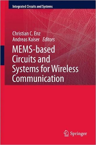
MEMS-based circuits and systems for wireless communication
MEMS-based Circuits and platforms for instant verbal exchange presents finished assurance of RF-MEMS expertise from equipment to procedure point. This edited quantity areas emphasis on how procedure functionality for radio frequency functions will be leveraged via Micro-Electro-Mechanical structures (MEMS). insurance additionally extends to leading edge MEMS-aware radio architectures that push the opportunity of MEMS expertise extra forward.
Analog Circuit layout comprises the contribution of 18 tutorials of the seventeenth workshop on Advances in Analog Circuit layout. every one half discusses a particular to-date subject on new and priceless layout rules within the quarter of analog circuit layout. each one half is gifted through six specialists in that box and cutting-edge details is shared and overviewed.
Computational Nanotechnology Using Finite Difference Time Domain
The Finite distinction Time area (FDTD) procedure is a vital instrument in modeling inhomogeneous, anisotropic, and dispersive media with random, multilayered, and periodic basic (or equipment) nanostructures because of its beneficial properties of maximum flexibility and simple implementation. It has ended in many new discoveries bearing on guided modes in nanoplasmonic waveguides and keeps to draw consciousness from researchers around the globe.
Multi-dimensional Optical Storage
This booklet offers ideas and functions to extend the cupboard space from 2-D to three-D or even multi-D, together with grey scale, colour (light with various wavelength), polarization and coherence of sunshine. those actualize the advancements of density, means and knowledge move cost for optical information garage.
- Microwave Transistor Amplifiers: Analysis and Design
- Microwave Transistor Amplifiers: Analysis and Design
- Simulation-Driven Design Optimization and Modeling for Microwave Engineering
- Foundations of Oscillator Circuit Design (Artech House Microwave Library)
- CMOS RF Circuit Design for Reliability and Variability
Extra resources for High-order modulation for optical fiber transmission
Example text
Chromatic dispersion tolerance of coherent optical communication systems with electrical equalization. In: Proceedings of Optical Fiber Communication Conference (OFC), OWB2 (2006) 45. : Coherent detection method using DSP for demodulation of signal and subsequent equalization of propagation impairments. IEEE Photonics Technology Letters 16(2), 674–676 (2004) 46. : Equivalence between preamplified direct detection and heterodyne receivers. IEEE Photonics Technology Letters 3(9), 835–837 (1991) 47.
Having now discussed some fundamental components used in the various transmitters for high-order modulation, some basics for multi-level signaling are briefly presented in Sect. 2. Afterwards, the transmitters for particular modulation formats are described in detail. M, M = 2m ). 23) and with amplitude and phase states given by abk = 2 q2 q bki + bk , ϕbk = arg bki , bk . 24) One of the M = 2m symbols is assigned to each symbol interval (denoted by the integer k, which has a range of 1 to ∞) of length TS = m · TB , where r B = 1/TB is the data rate.
43) 2 k k arg i k , qk · p (t − kTS ) . 44) are generally applicable to any QAM constellation, and i k and qk represent the normalized symbol coordinates. For Square 16QAM, for instance, it holds i k ∈ {−1, −1/3, 1/3, 1} and qk ∈ {−1, −1/3, 1/3, 1}, and the nor- 40 2 Transmitter Design malized symbol coordinates i k and qk are related to the data bits d1k , d2k , b3k , b4k as defined by the bit mapping shown in Fig. 3. 3 Relation between the data bits d1k , d2k , b3k , b4k , the normalized symbol coordinates i k and qk , the normalized symbol amplitudes and the symbol phases for Square 16QAM after differential quadrant encoding for the bit mapping defined in Fig.


